SR-1 CG Radar

User Manual

SR-1 is intended to enhance riding safety but cannot replace the rider's own attention and judgment. Always stay alert and ride safely.

Package List

Product Installation

Radar Module Installation

Adjust the radar module according to the actual installation conditions and install it horizontally. The installation height should be 30 –100 cm above the ground.

Bendable base for effortless installation.

The warning light features automatic brightness control. Do not cover it, as this may affect visibility and alert performance.

Warning Light Installation

Standard Adhesive Method: Attach the warning light directly to a suitable position on the original mirror.

Bracket Mounting Method: Use the dedicated M10 warning light bracket and install it onto the M10 screw hole of the original rearview mirror. After securing the mirror, attach the warning light to the surface of the bracket.

*Please ensure the warning light is installed without obstructing the rider's line of sight.

Product Wiring Diagram

Please complete the wiring as shown in the product wiring diagram, power on the system, and check if the indicator light turns on normally.

Power Connector

Note. Align the connector with the mark before plugging it in. Then, insert and tighten the nut.

Main Harness Light Control Connector

Fuse Box (3A)

Connect the red wire to the motorcycle battery's positive terminal.

Connect the black wire to the motorcycle battery's negative terminal.

Connect the yellow wire to the motorcycle's ACC terminal.

Indicator Light Description

When a vehicle is following or overtaking from the rear side, the indicator on that side and at the rear will remain on.

Fast-approaching vehicle with potential collision: all warning lights flash rapidly.

Alert Strategy

BSD (Blind Spot Detection)

Warning Zone: Approx. 10 m behind your vehicle in the left and right adjacent lanes.
Alert Behavior: When a vehicle enters the blind spot on one side, the warning indicator on that side illuminates.
Covered Scenarios: Being overtaken, riding alongside at a similar speed, and other blind-spot situations.

LCA (Lane Change Assist)

Warning Zone: Approx. 70 m behind your vehicle in the left and right adjacent lanes.

Alert Behavior: When the trigger conditions are met, the warning indicator on the corresponding side turns on.
Dynamic Timing: The higher the relative closing speed, the earlier (and farther away) the alert is triggered. At lower closing speeds, the alert distance is shorter.

Default Alert Strategy:

Low speed, <20 km/h: Alerts when a risk is detected within approx. 3 seconds.

Medium speed, 20-60 km/h: Alerts when a risk is detected within approx. 5 seconds.

High speed, >60 km/h: Provides an early alert when a risk is detected within approx. 10 seconds.

RCW (Rear Collision Warning)

Warning Zone: Approx. 10 m directly behind your vehicle.

How it works: If a vehicle approaching from behind reaches the time-to-collision (TTC) warning threshold, the system triggers an alert and all warning indicators flash.

AOA (Active Overtake Alert)

Warning Zone: Approx. 10 m behind your vehicle in the left and right adjacent lanes.
How it works: After you overtake a vehicle, the system monitors the adjacent-lane blind spot. If a vehicle is detected on that side, the corresponding warning indicator illuminates.

※ Enabled by default; no on/off setting is available.

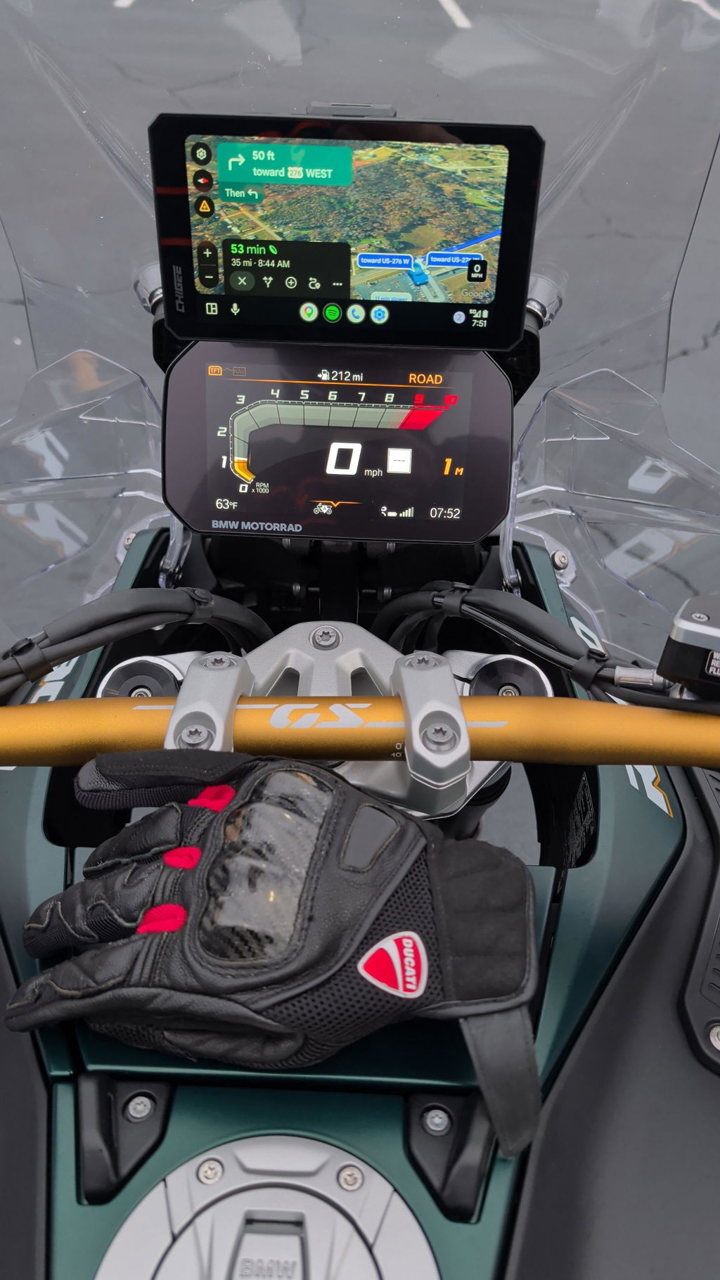
Pair with the Chigee Display for use

Open Settings → Function → Blind Spot Monitoring, select Millimeter-wave Radar, and follow the on-screen instructions to complete pairing.

Fast-approaching vehicle with potential collision: all warning lights flash rapidly.

After the radar is enabled, the display unit will automatically disable visual blind spot detection, providing more accurate blind spot alerts.

Specifications

System Specifications

Operating Voltage

12–18V DC

Operating Temperature

-25°C to +65°C

Power Consumption

≤ 3 W

Waterproof Rating

IP68 & IP69

Operating Frequency

77GHz

Data Refresh Rate

15 Hz

Wireless Connectivity

Bluetooth BLE 5.0

Radar Module Dimensions

42 x 42 x 18.5 mm

Detection & Measurement Performance

Maximum Detection Range

70 m

Speed Measurement Range

±200 km/h

Speed Resolution

1 km/h

Distance Measurement Accuracy

±0.15 m

Angle Measurement Accuracy

±3°

Antenna & Radar Architecture

Antenna Configuration

2 Transmit / 4 Receive (2 Tx, 4 Rx)

Horizontal Detection Angle

110°

Vertical Detection Angle

90°

Algorithm & Alert Support

Supported Safety Alerts

BSD / LCA / AOA / RCW

Adjustable Activation Speed

0 / 10 / 30 / 50 km/h

TTC Risk Assessment Threshold

Dynamic tracking strategy